Glasshouse Selector Remote Control Kit
The all-new Glasshouse Selector Remote Control Kit is to be used in conjunction with the Glasshouse Remote Control kit for Alps & TKD motorised potentiometer. As it makes use of the power supply and the RF sensor on that board, so note this kit will NOT WORK on its own.
So for all those you already have the remote control kit for the motorised kit you can now make a complete pre-amplifier whereby the volume and the input selector can work remotely from one handset.
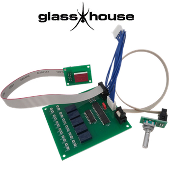
The selector switch provides full control of 5 stereo RCA signal inputs by way of the remote control handset. you can also manually select your input by turning the rotary encoder controller, attached to the main selector board by a 30cm ribbon cable for easy location at the front of your chassis. Your stereo RCA inputs are numbered 1 to 5 and these are displayed by way of the RED figure of 8 display fitted on its own PCB which is also attached to the main selector board by way of a 30cm ribbon cable. All 3 cables are terminated with different size connectors and will only fit one way round so it is impossible to wire it up incorrectly. For those who do not want to use the rotary encoder or the figure of 8 display, that is fine just don't connect it up. Please note we only provide the full kit.
The kit includes all you need to set everything up, all the cables are assembles and the PCBs are populated. However, you will need to provide your own signal wire, solder, RCA sockets. and fixings. The only soldering required is to connect up you RCA signal inputs and outputs. These are labelled on the selector PCB IN1R, IN1L.... OUTR and OUTL and PAD13 to 24 for the earth connections, see below for the full wiring list.
The Glasshouse Selector PCB is connected to the Glasshouse Motorised Potentiometer remote board by way of 30cm long cable terminated with the push on Molex 5 Way, 1 Row, Straight PCB Header connectors. If you already have the potentiometer PCB please check that the 5 pin Molex white male connector is fitted near the AC1 and AC2 solder pads. If it wasn't as I believe some weren't please let us know in your order comments and we will include one free of charge so you can solder it in. The cable provides the power and the signal from the RF sensor to control the selector board.
Dimensions:
Main Selector PCB - 82mm x 90mm x 22mm (height with components fitted), 4 corner 3mm diameter holes with centres 74.5mm x 82mm
Encoder PCB - 18mm x 30mm x 52mm (height with components fitted)
Encoder - shaft 6mm diameter x 18mm length, bush 7mm diameter x 7.5mm height
Figure of 8 Display PCB - 40mm x 29mm x 28mm (height with components fitted), 4 corner 3mm diameter holes with centres 33.5mm x 22.5mm
Description by the designer Nick Gorham:
- Populated mains selector PCB
- Populated encoder PCB
- Populated figure of 8 display
- Terminated cable - main selector PCB to Motorised PCB
- Terminated ribbon cable - (2 x 3 connector) - main selector PCB to encoder PCB
- Terminated ribbon cable - (2 x 5 connector) - main selector PCB to figure or 8 display PCB
- We do not provide instructions please refer to the video and this page.
Main Selector PCB Solder List:
- IN1R - input 1, right channel signal
- IN1L - input 1, left channel signal
- IN2R - input 2, right channel signal
- IN2L - input 2, left channel signal
- IN3R - input 3, right channel signal
- IN3L - input 3, left channel signal
- IN4R - input 4, right channel signal
- IN4L - input 4, left channel signal
- IN5R - input 5, right channel signal
- IN5L - input 5, left channel signal
- OUTR - output right channel signal - to volume control
- OUTL - output, left channel signal - to volume control
- PAD13 - input 1, right channel earth
- PAD14 - input 1, left channel earth
- PAD15 - input 2, right channel earth
- PAD16 - input 2, left channel earth
- PAD17 - input 3, right channel earth
- PAD18 - input 3, left channel earth
- PAD19 - input 4, right channel earth
- PAD20 - input 4, left channel earth
- PAD21 - input 5, right channel earth
- PAD22 - input 5, left channel earth
- PAD23 - output right channel earth - to volume control
- PAD24 - output, left channel earth - to volume control