Passive crossover parts QualitySpec determination by P A Coupe

P A Coupe from Reference Fidelity Components has been an associate of Hi-Fi Collective for some years. A keen and passionate enthusiast of all things Hi-Fi and he spends hours listening to his creations to wonderful effect. So have a read of his wisdom as he takes a view on loudspeaker crossovers.
Passive crossover parts Quality/Spec determination – Part 1
Passive crossovers are one area of hi-fi that will elicit just as many opinions as what sort of cartridge “sounds best” or how much to invest in a DAC or even have analogies to the (not so) great cable debates. The truth is sometimes hard to come by, mostly because a) manufacturers are not always keen to part with their own findings on the matter and b) it is one area of DIY where just about anyone who can learn to solder can fiddle about with swapping things out, and curiously report back that they almost always hear an improvement!
The first part is easy to deal with. Some manufacturers invest heavily in R&D for their passive designs even going as far as to develop some of their own components. Verity Audio, for example, use their own bespoke iron laminated cored low DCR inductors, because they know that’s one area where big compromises are usually made in mass-produced loudspeakers. Others build for maximum profit and use a mix of electrolytic for cheapness with perhaps a box capacitor in the output stage.
One thing is for sure and that’s there’s no standard as such, so where does that leave the inveterate tweaker?
The answer is actually quite logical and can be broken into several areas for consideration:
- Quality of drive units and enclosure;
- The complexity of crossover;
- Design of the circuit;
- Budget.
Point 3 above is the most under-rated, misunderstood, and overlooked part of the equation, so let’s start with that.
The crossover circuit is not just the board containing components that are used to drive your speakers when fed by an amp. The circuit needing consideration is made up of:
- Amplifier output stage;
- Crossover;
- Loudspeaker motor - which being a voice-coil within a magnetic gap has characteristics including equivalent inductance, a rising impedance with frequency, and limitations on power handling as well as the overall characteristic sensitivity of the loudspeaker, and in the case of woofers especially, a characteristic defined by the electro-mechanical properties of the driver (resulting from mechanical inertia) which determine back EMF generated within a specific cabinet design which in turn determine things like power dissipation in the driving amplifier needed and hence damping factor aimed for).
Decision making
The easiest place to start is looking at the quality and pair matching tolerance of the drive units. It is pretty pointless to replace with high-quality parts in any area of the crossover if the drivers are poorly pair-matched and of an inexpensive nature to begin with and the crossover is poorly designed. Throwing good money at parts won’t alter the sound characteristics such as linearity, phase etc. Just use anything as any benefits to not using bipolar electrolytic are usually outweighed by driver limitations of poor frequency response, limited power handling, and poor choice of materials and construction to start with.
Once you consider systems using reasonable quality close matched drive units and reasonably well-designed crossovers then it’s time to consider the overall circuit characteristics, particularly the system impedance and required damping factor (DF) for control of low frequencies. As DF reduces, the speaker response tends to follow the impedance response as well as being very poorly electrically damped causing smearing of details and bass overhang. Poor choice of inductors here can lead to intermodulation distortion, worsening of sound quality, and high distortion.
In all other respects, the complexity of the crossover has a marked impact on component quality in three major areas. The more complex the passive crossover, the more critical things such as close tolerance parts matching, the equivalent series resistance and stability of capacitors, and the DCR and saturation point and coupling field of inductors all become.
The thing worth remembering is that resistors are the least reactive part and just about anything can be used providing it has properly rated power handling, close tolerance, and has low thermal drift (this is the “PPM” rating of the resistor).
Passive crossover parts Quality/Spec determination – Part 2
Capacitors
Quality of capacitors: Nothing special per se is required except reasonable quality, properly rated, low ESR Capacitors the best, being polypropylene film & foil, closely followed by metallised Polypropylene. Unlike PIO types and other forms of electrolytic capacitors, these stay stable under load, stable with temperature, and do not drift or exhibit climbing ESR or failure with age
No decent crossover uses electrolytic UNLESS it is impractical or impracticable on grounds of the high values that may be needed. Large capacitance values mean that overall plate size increases so the size of the capacitors increases. Electrolytics can keep sizes sensible for the LF. In cases where the speaker system might cost “X” amount, you may not wish to spend “X/5” say for bunches of quality polypropylene film capacitors to make up say 120uF values that might be needed in the bass.
In cases like these, providing the ESR and voltage rating is accounted for, there’s nothing wrong with using quality electrolytic, hand-matched to within 5%, and paralleled to bring DCR down to ultra-low levels unless you particularly need some flattening of the 2nd or 4th poles of a low pass filter. Just remember that these will drift with age and as they cost peanuts, you’re best advised at refreshing them every 10 or 15 years as they only cost a few pounds at most. Contrary to popular urban myth, modern electrolytic can have quite low ESRs. A typical value for a 25uF capacitor might be 0.15 to 0.2 Ohms
In all other areas of a crossover, there is no excuse not to use polypropylene capacitors of close tolerance. It is pointless having drive units pair-matched to within 1% at production then to use a 10% tolerance cap OR poor quality capacitors...you will not achieve the potential of the loudspeaker system and this will affect the finesse of the imaging and response of the stereo pair not to mention things like slightly skewing tolerances for phase matching of not properly pair-matched to at least 5% or better (2nd order) with 1% being required for best results in higher (4th order) crossover components.
The argument of using the best quality for series parts and “el cheapos” for parallel parts is only partially true. Remember, the speaker is in parallel to your amplifier outputs and is part of a larger circuit so to some extent, all parts matter. Sensibly though, reserve the highest quality caps for the series sections if mid-woofers/ranges and tweeters.
Shunt caps need to be adequately rated for the power they’re asked to dissipate and just about all polys going today are sold as either 250v, 400v, or 630v rated. All any crossover needs, at the very most is 400v rated. There are one or two electrical arguments for using the higher rated 400 over the perfectly adequate 250v rated in terms of potentially lower distortion for higher rated caps but in reality, the additional benefit may not be audible as the percentage improvements are very slight indeed. The advice I’d offer is if there is space to use them, and there’s not much in it budget-wise then use the 400v rated ones if you want but the chances of actually having any real benefits over a 250v rated one are debatable. The higher-end more complex crossovers sometimes use them as it is deemed good practice to adopt the best possible solutions where complexity could otherwise have a cumulative effect that may just be audible. What is true is that using great big 630v rated caps has little to no benefit over 400v rated ones in crossover use, they take up much more room and cost significantly more, so unless you must use them, stick with 250 or 400v rated and save your money. For some though the looks of a crossover is something to show off, so some will wish to squander on these much larger parts for the looks alone.
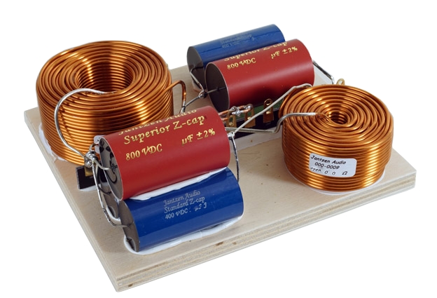
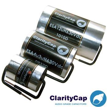
Quality is seldom equated to cost alone. Remember that. A close tolerance adequately rated 250v budget poly will have an identical effect on impedance with frequency as its more expensive cousin so it does much the same job. The differences to look for that are meaningful are things like lead out leg gauge, reliability of lead-out connections, the plate design (is single or the more usual double plate designs), and whether the paper-in-oils or other exotic things actually have any effect. The advantage with the thicker lead out legs I’ve found with older crossovers in for refurbishment is that they’re less likely to fail due to corrosion at solder joints and have a larger contact area and lower resistance (although the latter’s arguably meaningless for comparing an inch or two of thicker wire to a thinner one). I shun really thin lead out legs for quality crossovers hence I no longer use some makes of the cheaper designs. Prototyping with these also shows up reliability issues after they’ve been used a few times. In general, just buy and use reasonable quality caps for the series side of things. I recommend caps like Claritycap ESAs, CSAs, or Jantzen Standard Z-Caps. For shunt duties on 2nd or 4th order poles you Jantzen Standard Z-Caps of Claritycap SAs. For a compact fitment and excellent sonics, Mundorf’s Evo series is also very highly recommended.
If you wish to go to a higher spec you won’t find any difference in measured frequency response but you may find where really high-quality drive units are used, that low-level fine detail can sometimes be a little more precise and detailed with some higher quality caps. For 2nd order networks where the component count is relatively low, and where high-quality drive units are concerned, it does not hurt to use a cap like the Mundorf Supreme or Claritycap CSA or the Mundorf Evo range (if ultra-low ESR is desirable), so the obvious application here might be for tweeters. ESAs or equivalents are more than adequate for mids.
Huge cast caps using exotic materials and making claims about microphonics and musicality simply cannot be evidenced so in the humble opinion of this loudspeaker engineer do not represent value and where things like POIs are concerned, are storing up issues as they age. I do not recommend them. They are best left to the “must-have” bucket list for no other reason than some wish to purchase for the name and kudos but really you are better advised putting hard-earned where it matters most and achieving the best results by saving exotic builds for the inductors.
Passive crossover parts Quality/Spec determination – Part 3
Inductors
The basics are power rating, characteristics of each type, limitations of space, DCR aimed for, EMI field coupling control, design, and placement.
The first consideration is value. Low value (ie small mH) inductors that carry low current and to be used in the mid or HF are usually best specified as air cores as the air in the core does not saturate, does not exhibit hysteresis, and exhibits low, practically non-existent distortion. The counter to that is that they can have a relatively wide inductive coupling field which rises with the current passed and size of the inductor.
When designing crossovers the designer takes into account (or should) the DCR of the inductor when considering the crossover slope design. If unsure and are upgrading a crossover the rule of thumb is to replace like for like DCR values (or within say 0.25Ohms of such). Where larger values are required, air cores are not ideal and unless you have plenty of space and where mH values are low enough to keep the number of windings modest enough to ensure low DCR. Of course, the DCR of the air core can indeed be used as part of the slope shaping so you are free to play around to see how the DCR value might affect the slope. For low frequencies, the bass inductor is a special case and needs further explanation:
Bass Inductors
These are in series between the amplifier and the woofer and as such, their series resistance is also in series such that it is additive to the output impedance of the driving amplifier and all losses in between from loop resistance of the speaker cable to all connections. This matters. Where high inertia (typically anything much above 8 inches with a longish throw) drivers are concerned, the inertia acts as a reverse generator, forcing the amp to dissipate the energy of the back emf. Where the sum of output impedance is high compared with the drivers minimum impedance (for an 8 Ohm woofer this is typically between 6.5 and 7.5 Ohms) then the frequency response will be skewed as it will tend to follow the impedance profile at low frequencies and have a tendency to “overhang” and mess up bass timbre giving a muddled, slow sounding lumpy bass. Intermodulation distortion will also rise.
The trick here is to lower the series inductor DCR to as low as possible as it is the single highest loss between the amp and drive unit. You’re already on a hiding to nothing if using a long throw or large woofers driven by high output impedance amps like valve SET amps with no feedback or even some PP designs using nowhere near enough feedback. The output impedance of some currently manufactured valve amps can be as high as 3 Ohms. You’re ideally looking for a damping factor of more than 7 when considering the cable and passive crossover losses.
The stated DF at the amp is meaningless without considering these things. It may start out as say 200 at the amp (quoted into an ideal 8-ohm load) but after adding crossover losses and accounting for minimum driver impedances at low frequencies, it can easily end up at just 3! With the 8 ohm driver, you’re already below that if you use a zero feedback valve SET amp. They were designed for high-efficiency horns, typically employing compression drivers but if choosing wisely there are some SET amps that employ very high levels of feedback purely to get output impedance down. These are the better ones to use with conventional passive loudspeaker designs.
Those who are way ahead of me will have already worked out that even a SS amp with vanishingly low output impedance (say 0.05Ohms) which claims a damping factor of say 160 stated as into an 8-ohm load, doesn’t really have that amount at all...it is wholly misleading. Let’s use our example of a 6.5-ohm driver (impedance at say 40Hz). Add 0.3 Ohms for cable loop resistance and connection losses, then ass another 0.5 ohms (typical) for a largish ferrite core inductor and you have 6.5/0.8 = true damping factor of just 8.
What’s the answer? Low DCR inductors. To cut to the chase the best examples for sound quality which meet the specification in all respects of low DCR, negligible hysteresis, low coupling field, and low distortion are laminated core inductors using core materials such as grain-oriented M6 steel in E&I or similar configuration. For typical 2 to 3mH values, these can be reasonably economically designed and made to offer just 0.1 or less DCR which is a significant uplift in bass control and very low levels of LF intermodulation distortion. Our example above would go from a DF of 8 to one of 6.5/0.4 = 16, so a doubling of damping factor which in this case would be audible in terms of bass control and also lend a little more system efficiency to the design. Good examples of these include Mundorf’s “Zero Ohm” inductors and Reference Fidelity Components’ “HDF” E&I cored bass inductors.
Passive crossover parts Quality/Spec determination – Part 4
Resistors
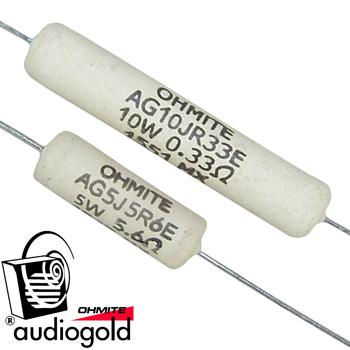
The simple and short answer is to use anything you like as long as it is rated above the maximum it is called to dissipate (I usually use 10w ratings for 5w needs for example) to reduce any thermal drift. For tweeter sections, use low PPM close tolerance designs hand-matched to at least less than 5% and preferably to within 1% with a PPM rating under 100 preferably and twice the wattage rating needed.
As the humble resistor is the least reactive part of any crossover. “Non-inductive” types costing more are really not offering much, if any audible advantage unless in very high values, probably rarely associated with passive crossovers...they’re simply not called for when measured inductance can be as low as 0.002mH or less for typical values of standard wire-wounds used so they won’t become anything like reactive enough to matter at audio frequencies. Ohmite, Vishay, Mills, Mundorf, and Janzten are all fine. Avoid METOX only because some have quite high thermal drift values so if they have to be used, they are best reserved for very low current applications.
Hopefully, that sheds a little more light on the minefield that is choosing passive crossover parts.
P A Coupe
September 2020-09-23
