aeco ABC-1451 Male 50-ohm Beryllium Copper BNC plug, Gold-plated
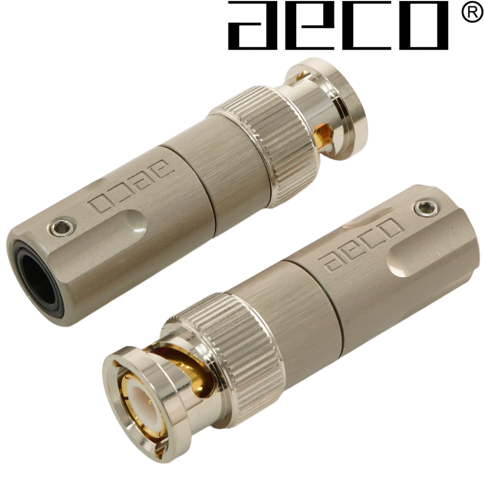
The ABC-1451 BNC plug maintains consistent conductor and insulation diameter ratio for optimal transmission performance. With the conductors being connected via soldering or crimping and the contact material being high-purity beryllium copper, nickel-free plating.
Ensure that the connectors and cables have matching specifications and impedance. Examples of standard systems: Japan: 4C, 5C & USA: RG-59, RG-6U.
Main contact pin supports various secondary pins for increased compatibility. Secondary pins feature a cross-cut and shrink-fit design.
Materials & Finish
-
Contact Pin: Beryllium Copper (C17300), minimum 97% copper content, 10µ" gold plating, no nickel base.
-
Body & Shell: Brass Zinc Alloy (C3604), gold or satin nickel plating with topcoat.
-
Spring & Washer: Steel, nickel plated.
-
Screws: Stainless Steel (SUS304), natural finish.
Mechanical Structure
-
Main contact pin uses barb hooks to anchor into insulation.
-
Secondary contact pin is secured using the crimp method.
-
Shell body and insulation interlock using barb hooks; middle piece fixed with punch riveting.
-
Front shell is riveted to the body and can rotate independently via a spring and washer.
-
Rear and middle parts of the shell are screwed together and secured to the cable using a screw.
Assembly Instructions
1. Cable Preparation
1.1 For Cable OD < 7.5mm
-
Place the rear shell part (301) on the cable. Remove the sleeve (311/312) if necessary.
-
Peel back the shield by 6.0mm.
-
Remove the braid and dielectric by
X - 2mm, where X = cable OD including braid. -
Spread the braid radially with the core pointing vertically. Spread diameter ≈ 12.0mm.
-
Remove any aluminium foil and dielectric in the spread area.
-
Ensure the core protrudes 3.0mm beyond the spread braid.
1.2 For Cable OD 7.5–10.5mm
-
Peel back the shield by 20.0mm.
-
Remove braid and dielectric by
X - 2mm. -
Place the rear shell part (301) on the cable. Remove the sleeve (311/312) if necessary.
-
Spread the braid radially with the core pointing vertically. Spread diameter ≈ 12.0mm.
-
Remove any aluminium foil and dielectric in the spread area.
-
Ensure the core protrudes 3.0mm beyond the spread braid.
2. Contact Pin Installation
-
Select the appropriate secondary contact pin:
-
201: Inner diameter = 1.3mm after shrink
-
202: Inner diameter = 0.9mm after shrink
-
203: Inner diameter = 0.5mm after shrink
-
-
Chamfer the cable core surface by chipping or milling.
-
Connect the secondary contact pin using one of the following methods:
-
Crimping: Clamp the pin and insert onto the centre conductor.
-
Soldering: Clamp the pin and solder it to the core.
-
3. Final Assembly
-
Insert the secondary contact pin and cable into the main contact pin in the shell’s middle section (100).
-
Ensure the braid is fully spread and radial.
-
Lock the rear part of the shell (301) into the middle shell section.
-
Secure the cable to the shell’s back using screw (321/322).
Soldering Temperature Guidelines
-
350°C — Maximum 20 seconds
-
400°C — Maximum 15 seconds
-
450°C — Maximum 10 seconds
Specifications:
Electrical Characteristics
-
Impedance: 50 ohms
-
Frequency Range: Up to 1 GHz
-
VSWR: ≤ 1.2
-
Contact Resistance: Less than 0.1 milliohm
Physical Dimensions
-
Cable hole without sleeve: 10.5mm
-
Cable hole with sleeve: 6.5mm or 8.5mm
-
Maximum Outer Diameter: 14.5mm
-
Total Length: 42.0mm
Cable Size Compatibility
-
Centre Conductor: Less than 1.5mm
-
Insulation Outer Diameter: Greater than 3.0mm
-
Woven Shield Outer Diameter: Greater than 7.5mm
-
Outer Plastic Sheath OD: Less than 10.5mm
Sold as a pair.
PRICE (pair)
£
69.23 +vat +p&p