aeco ABC-1471 Male 75-ohm Beryllium Copper BNC plug, Gold-plated
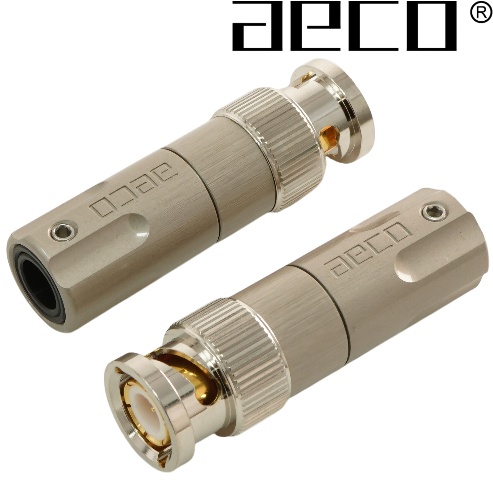
Designed for 75 ohm systems, the ABC-1471 BNC plug maintains consistent conductor and insulation diameter ratio for optimal transmission performance. With the conductors being connected via soldering or crimping and the contact material being high-purity beryllium copper, nickel-free plating.
Specifically engineered for 75 Ω use—ideal for video and SAT systems.
Main contact pin supports various secondary pins for increased compatibility. Secondary pins have cross-cut, shrink-fit design; support both solder and crimp methods.
Materials & Finish
-
Contact Pin: Beryllium Copper (C17300 ≥97% Cu), 10 µ″ gold plating (no nickel)
-
Shell and Body: Brass Zinc Alloy (C3604), satin-nickel + topcoat
-
Spring & Washer: Steel, nickel-plated
-
Screws: Stainless Steel (SUS304), natural finish
Mechanical Structure
-
Main contact pin uses barb hooks into insulation during assembly
-
Secondary pin secured via crimping method
-
Body and insulation interlock via barb hooks; middle shell piece fixed by punch riveting
-
Front shell riveted with spring & washer; independently rotatable
-
Middle and rear shells locked by screwing; secured to cable with screw
Assembly Instructions
1. Cable Preparation
1.1 For Cable OD < 7.5 mm
-
Fit rear shell part (301); remove sleeve (311/312) if needed.
-
Peel shield 6.0 mm back.
-
Remove braid + dielectric by
X − 2mm (X = cable OD) -
Spread braid radially (~12 mm diameter); remove foil/dielectric in area.
-
Ensure core protrudes 3.0 mm beyond braid
1.2 For Cable OD 7.5–10.5 mm
-
Peel shield 20 mm back.
-
Remove braid + dielectric by
X − 2mm. -
Fit rear shell (301); remove sleeve (311/312) if needed.
-
Spread braid (~12 mm diameter); remove foil/dielectric.
-
Ensure core protrudes 3.0 mm beyond braid
2. Contact Pin Installation
-
Select secondary contact pin (2 of each):
-
201: ID 1.3 mm
-
202: ID 0.9 mm
-
203: ID 0.5 mm
-
-
Chamfer cable core tip via chipping or milling
-
Choose method:
-
Crimp: Clamp pin and insert onto conductor.
-
Solder: Clamp and solder pin to conductor.
-
3. Final Assembly
-
Insert contact pin and cable into main pin inside shell (100).
-
Ensure braid is radial; lock rear shell (301) into middle shell
-
Secure cable to rear shell with screw (321/322).
Soldering Temperature Guidelines
-
350 °C for ≤ 20 s
-
400 °C for ≤ 15 s
-
450 °C for ≤ 10 s
Specifications:
Electrical Characteristics
-
Impedance: 75 Ω
-
Frequency Range: Up to 1 GHz
-
VSWR: ≤ 1.2
-
Contact Resistance: < 0.1 mΩ
Physical Dimensions
-
Cable hole without reducer: 10.5 mm
-
Cable hole with reducer: 6.5 mm or 8.5 mm
-
Max OD: 14.5 mm
-
Total Length: 42.0 mm
Cable Size Compatibility
-
Centre conductor: < 1.5 mm
-
Insulation OD: > 3.0 mm
-
Shield OD: > 7.5 mm
-
Sheath OD: < 10.5 mm
Sold as a pair.
PRICE (pair)
£69.23 +vat +p&p