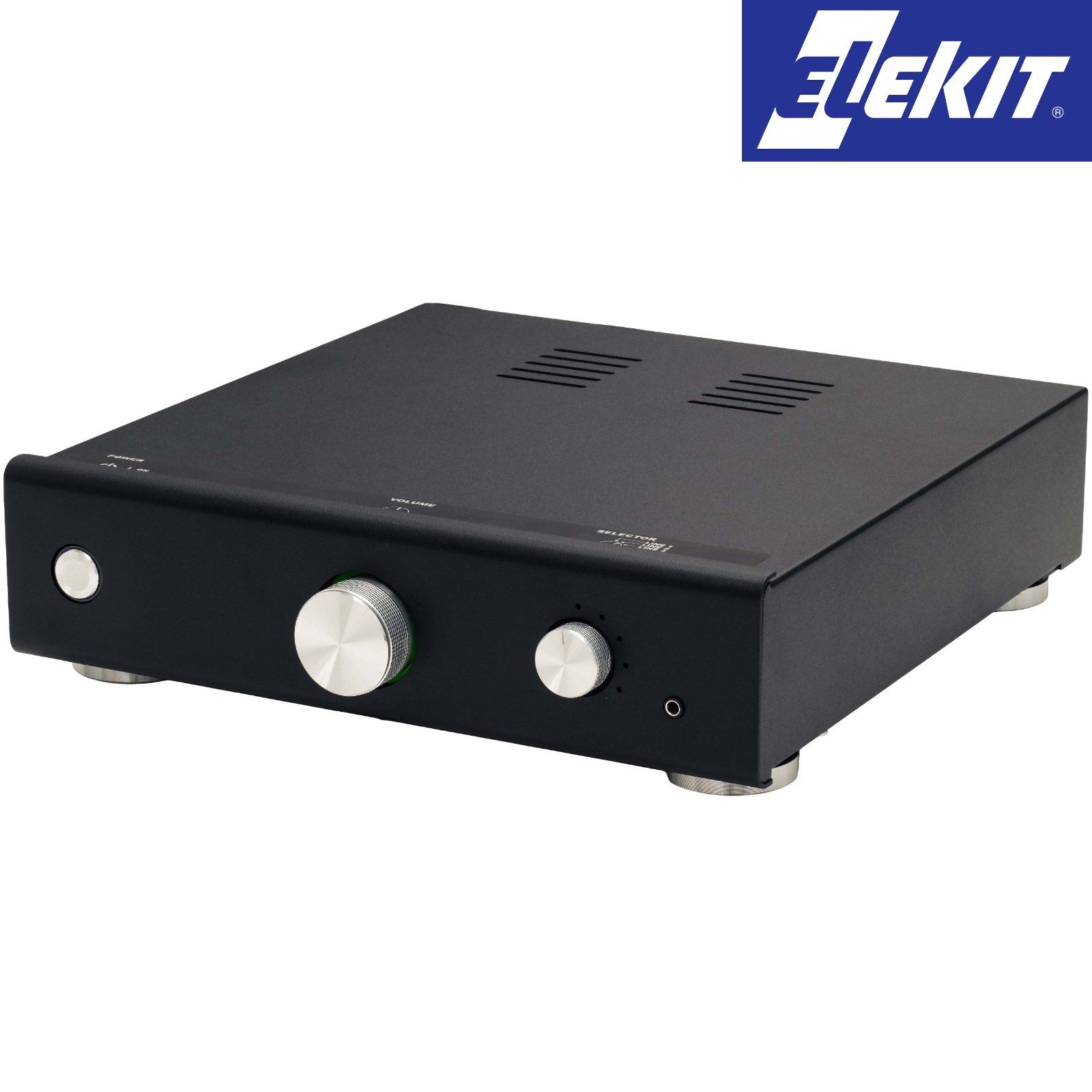
Elekit TU-8450 Tube Pre-amplifier Kit with Phono Stage

The all-new Elekit TU-8450 Valve Pre-Amplifier Kit is a vacuum tube preamp kit that incorporates a solid-state phono equaliser stage, accepting both MM and MC inputs. This kit is the upgraded successor to the popular TU-8500 and is perfectly coupled with the TU-8400, matching its matt black finish.
A CR-type RIAA equaliser circuit for smooth sound quality
A CR equaliser with an op-amp is adopted. This filter uses a complex network of capacitors and resistors (CR), to attenuate different frequencies, resulting in a more accurate RIAA compensation. The op-amps used are the 2068DD installed via IC sockets, making op-amp swapping easy. The preamp supports both MM and MC cartridges. As it is an op-amp circuit, the noise floor is incredibly low.
Flat amplifier stage consisting of 12AU7
12AU7 valves are used for the line amp stage, allowing you to enjoy the sound difference by rolling 12AU7 valves from various manufacturers.
REC-OUT terminal
The pre-amp can receive three line inputs via RCA sockets (pairs), one line input via a 3.5mm stereo jack, and one phono input via an RCA socket (pair). Additionally, there is a record out via RCA sockets, useful for recording or when using an external amplifier.
Ample space for a larger coupling capacitor
The kit provides a high-quality polypropylene capacitor for the all-important decoupling capacitor; however, if you wish to upgrade to a large audio-grade part, there is plenty of room to do so. For the upgrade the value is 0.47uF 200Vdc, and the maximum size 36mm in length and 20mm in diameter.
Specifications:
Phono Equalizer Amp Stage
- Input resistance: 47kΩ (MM) , 100Ω (MC)
- RIAA equalization: ±0.5dB or less (20Hz-20kHz)
- Max. output voltage: 7V rms (1kHz)
- Gain (1kHz): 36dB (MM) , 63dB (MC)
- Residual noise (IHF-A): 20uV (MM), 290 uV (MC)
- Effective output impedance: Approx. 500 Ω
Flat Amp Stage
- Input resistance: Approx. 50Ω (Line 1-3), Approx. 10kΩ (Line 4)
- Max. Output Voltage: 17V rms
- Gain (1kHz): Approx. 13.6 dB (4.8 times) (JP1 and JP2 shorted: approx. 9.5dB (3 times)
- Fequency response: 5Hz - 200kHz (-3dB)
- Residual noise (IHF-A): 20 uV
- Effective output impedance: Approx. 600Ω
Overall
- Tubes: 2x 12AU7 included (ECC82 / E82CC / ECC802 / 6189 etc)
- PHONE IN: RCA jacks
- LINE IN: LINE 1, 2, 3: RCA jacks, LINE 4: 3.5mm phone jack (front)
- PRE OUT: RCA jack
- REC OUT: RCA jack
- 100V AC / 115V (110-120V) AC / 230V(220-240V) AC
- 50/60Hz, IEC standard 3-pin inlet
- Rated power consumption: 10W
- W253 x H73 x D272mm (incl. projections)
- Approx. 3kg (Assembled, excl. power cord)
PRICE (1 off) supplied with IEC lead (terminated with Japanese mains plug)
£475.00 +vat +p&p
UPGRADE OPTIONS
We do offer an upgrade kit. See the list below. These need to be purchased individually. Click on the links and add them to your cart. The total at the time of publishing is £153.88 + VAT
LINE PRE-AMP UPGRADE
| Part | Position | Quantity |
| RES-NB25-05W-1K0: 1K 0.5W Audio Note Niobium Non-Magnetic Resistor | R113, R115, R117, R217, R213, R215 | 6 |
| (CART 47K000B: 47K 0.4W Charcroft Z-Foil Resistor | R120, R220 | 2 |
| RES-NM25-05W-10K: 10K 0.5W Audio Note Tantalum Non-magnetic Resistor | R123, R223 | 2 |
| RES-NM25-05W-22K: 22K 0.5W Audio Note Tantalum Non-magnetic Resistor | R125, R225 | 2 |
| AMRG0.75-610: 220K 0.75W Amtrans AMRG Resistor | R124, R224 | 2 |
| RES-NM25-05W-220K: 220K 0.5W Audio Note Tantalum Non-magnetic Resistor | R106, R206 | 2 |
| ZN630-0,47: 0.47uF 630Vdc Mundorf MCap ZN Capacitor | C107, C207 | 2 |
| CAP-100-R-100U-16V: 100uF 16Vdc Audio Note Kaisei POLAR Electrolytic Capacitor | C106, C206 | 2 |
| CAP-100-R-50U-16V: 50uF 16Vdc Audio Note Kaisei POLAR Electrolytic Capacitor | C106, C206 | 2 |
| For the above 2 lines fit in parallel to achieve 150uF (16Vdc is within spec as only 5Vs) |
For those who like a challenge, there is room to fit a TKD Ko-on 2CP-2511 50K dual log potentiometer or a TKD (Ko-on) 2CP-601 50K dual log taper potentiometer. An understanding of the pin layout of the potentiometer and where those tags must be hard-wired to the PCB. Additionally, the fixing hole of the PCB needs to be enlarged, and the shaft must be changed to a "D" shape for the knob to fit. Some filing down would be required. We will soon be launching a video on this.
